Ideal for demanding bellows applications
Advanced engineering and design capabilities allow MS Bellows to manufacture edge welded bellows for a variety of critical reliability applications.
Using the latest manufacturing techniques and stringent process control, zero defect quality is maintained at a competitive price.
Several diaphragm contour designs are available, each with different functional properties.
The most popular are shown below.
Variations of each contour are available to complement your specific design application.
Our engineering staff will gladly provide you with recommendations and assistance.

Typical Applications
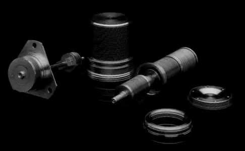
- Volume Compensators
- Pressure Transducers
- Shaft Couplers
- Aneroid Assemblies
- Mechanical Seals
- Pipe Expansion Joints
- Reservoir & Accumulators
- Vacuum Feedthroughs
- Pump/Compressor Components
Advantages
- Long Stroking Capability Per Unit Length of Bellows
- Short Compressed Length
- Long Fatigue Life Under Rigorous Operating Conditions
- High Volumetric Displacement Efficiencies for Tight Space Package Envelopes
- Excellent Operating Capacities in High Pressure and High Temperature Environments
- All-Welded Construction
- Excellent In-Service Corrosion Resistance
- Leak Tight to Helium Mass Spectrometer Requirements
- Large Sizes Available
- Materials and diaphragm profiles are available for a wide variety of applications


Diaphragm Contours & Spring Properties

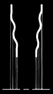
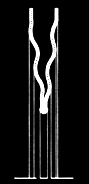
The nested ripple profile provides long stroking capability with linearity of stroke vs. pressure, plus very good resistance to pressure. This is the most commonly used design.
The flat plate design offers the best linearity of force output vs. pressure due to the more constant effective area. Stroking capability is fair and spring rate low.
-
Process
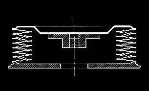
 Individual diaphragms are formed
 Inner diameter welded to form a convolution
 Convolutions are welded at O.D.s to make a bellows
 End-fittings are welded to the bellows to produce a complete bellows assembly.
- Standard Sizes
Outer Diameter (in.) Inner Diameter (in.) Effective Area (sq. in.) Material Thickness (in.) Spring Rate Per Convl’n (lbs./in./con.) Convl’n Pitch (in./con.) Max Stroke, Compression (in./con.) Max Stroke Extension (in./con.) .315 .135 .040 .002 340 .021 .014 .005 .388 .128 .052 .002 180 .026 .020 .007 .504 .218 .102 .003 400 .032 .023 .008 .568 .282 .142 .003 375 .033 .024 .008 .608 .228 .137 .0025 225 .043 .036 .012 .750 .250 .196 .0025 150 .038 .030 .009 .840 .340 .273 .003 187 .040 .031 .010 .893 .499 .380 .004 600 .036 .024 .008 .950 .670 .515 .0025 280 .027 .019 .006 1.010 .716 .591 .0035 1060 .031 .021 .007 1.122 .746 .688 .0025 210 .032 .024 .008 1.125 .535 .542 .005 1100 .053 .038 .013 1.158 .752 .724 .005 960 .040 .025 .008 1.250 .757 .791 .003 180 .033 .024 .008 1.325 .931 .999 .004 855 .033 .021 .007 1.348 .536 .697 .004 192 .060 .038 .013 1.379 .777 .913 .004 522 .042 .030 .010 1.430 .825 .998 .004 391 .056 .045 .015 1.467 1.262 1.462 .0025 455 .023 .015 .005 1.500 1.000 1.227 .006 2053 .032 .015 .005 1.526 1.154 1.410 .003 415 .030 .021 .007 1.625 1.125 1.485 .005 962 .045 .030 .010 1.644 1.244 1.638 .004 840 .040 .028 .009 1.817 1.246 1.813 .003 280 .032 .023 .008 1.937 1.400 2.187 .004 450 .050 .038 .013 2.006 1.696 2.691 .004 780 .034 .022 .007 2.100 1.400 2.405 .004 275 .050 .038 .013 2.419 1.702 3.334 .004 225 .049 .037 .012 3.000 2.000 4.908 .006 312 .076 .058 .019 3.478 2.876 7.942 .005 1350 .057 .042 .014 3.656 2.840 8.286 .005 825 .060 .045 .015 3.900 3.100 9.619 .005 630 .080 .065 .021 Properties such as spring rate can be adjusted to meet your specific requirement. This is partial listing of available die-sets for welded bellows. Please contact our staff for additional size requirements. Welded bellows up to 10.00 inches in outer diameter can be fabricated.- Design Equatons

K — Bellows Axial Spring Rate. The Ratio of Force to Stroke. (Lbs./In.)
K/C — Spring Rate per Convolution.
Ae — Bellows Effective Area. Equivalent Piston Area That Produces Axial Thrust. (Sq. In.)
A/K — Bellows Pressure Sensitivity. The Amount of Stroke Per Pressure Change. (In./Psi)
P — Convolution Pitch (In.)
Nc — Number of Convolutions
Lf — Free Length of Bellows. (In.)
y — Bellows Stroke or Deflection. (In.)
ΔP — Pressure Differential Across Bellows. (Psi)
ΔV — Fluid Volume Displacement. (Cu. In.)Consult Our Engineering Staff Regarding Your Specific Application Requirement
Contact Us To Get Started - Standard Sizes