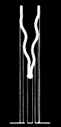
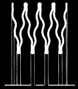
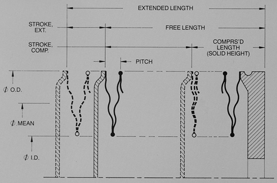
K — Bellows Axial Spring Rate. The Ratio of Force to Stroke. (Lbs./In.) K/C — Spring Rate per Convolution. Ae — Bellows Effective Area. Equivalent Piston Area That Produces Axial Thrust. (Sq. In.) A/K — Bellows Pressure Sensitivity. The Amount of Stroke Per Pressure Change. (In./Psi) P — Convolution Pitch (In.) Nc — Number of Convolutions Lf — Free Length of Bellows. (In.) y — Bellows Stroke or Deflection. (In.) ΔP — Pressure Differential Across Bellows. (Psi) ΔV — Fluid Volume Displacement. (Cu. In.)
Effective Area: Ae = (OD + ID)2 X .1963 Mean Diameter: φm = (OD + ID) / 2 Spring Rate: K = K/C / Nc Free Length: Lf = Pitch X Nc Stroke, Comp: y = Comp. Stroke/Conv. X Nc Stroke, Ext: y = Ext. Stroke/Conv. X Nc Stroke per PSI: A/K = Ae / Total Spring Rate Volume Displacement: ΔV = Ae X Total Stroke Force Output: F = K X y = ΔP X Ae Span: Convolution Depth = (OD-ID) / 2 Comp. Length (Welded) = 3 X Mat’l Thk. X Nc
Consult Our Engineering Staff Regarding Your Specific Application Requirement