
Ideal for demanding bellows applications
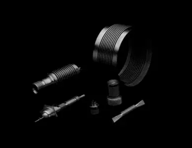
The need for greater precision in mechanical components has led to the development of high tensile properties in deposition alloys for use as a bellows material.
The MS-Deposition process produces a high density, high strength alloy with excellent spring properties.
Plated bellows permit a wide design latitude due to a variety of flexible configurations.
Each bellows is engineered and manufactured to the highest standards of quality and reliability.
MS Bellows continues to be at the leading edge of deposited bellows technology.

Typical Applications
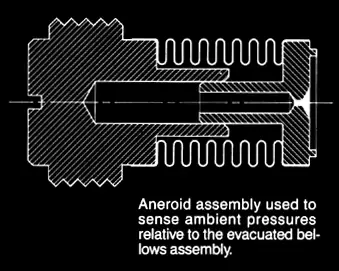
- Pressure Sensors
- Flexible Couplings
- Temperature Sensors
- Hydraulic Transmission with Amplification
- Axial & Rotary Seals
- Microwave Components
- Precision Miniature
- Assemblies
- Pressure Switches
Advantages
- Extremely small sizes can be fabricated by the MS-Deposition process. Bellows can be produced with O.D.s as small as .040 for miniature applications.
- Very fine sensitivities can be achieved for accurate instrument applications due to low spring rates and wall thicknesses as thin as .0003.
- High strength material allows for low hysteresis and maximum deflection applications.
- Long life in tough conditions.
- Constant effective area maintained through operating conditions.
- Uniform wall thickness and plating resolution yields controlled low tolerance and consistent spring rates.
- Proper convolution design tailors force-deflection characteristics to the specific application.
- Non-standard plated bellows can be produced with minimal lead time in a cost effective manner.


-
Process
 A mandrel is contoured with convolutions and end-type configuration
MS-nickel alloy is chemically deposited onto mandrel to the required thickness
The mandrel is dissolved out to leave the thin nickel-plated bellows
End-fittings are joined to bellows by soldering or adhesive bonding to make bellows assembly
- Standard Sizes
Outer Diameter (in.) Inner Diameter (in.) Effective Area (sq. in.) Material Thickness (in.) Spring Rate Per Convl’n (lbs./in./con.) Convl’n Pitch (in./con.) Max Stroke, Compression (in./con.) Max Stroke Extension (in./con.) .063 .039 .0020 .0005 135 .010 .005 .002 .063 .039 .0020 .0007 370 .010 .003 .001 .094 .054 .0043 .0008 160 .012 .005 .002 .094 .064 .0049 .0008 415 .012 .004 .0015 .125 .075 .0079 .0008 110 .016 .007 .002 .125 .075 .0079 .0010 215 .016 .006 .002 .125 .085 .0087 .0010 450 .012 .005 .002 .125 .065 .0071 .0010 120 .018 .008 .003 .188 .116 .0181 .0010 110 .022 .009 .003 .188 .116 .0181 .0013 242 .022 .008 .0025 .188 .128 .0196 .0010 195 .018 .007 .002 .188 .138 .0209 .0010 350 .016 .006 .002 .250 .154 .032 .0010 60 .030 .013 .004 .250 .154 .032 .0013 132 .030 .012 .004 .250 .712 .035 .0010 120 .025 .010 .003 .250 .190 .038 .0010 275 .018 .007 .002 .312 .192 .0499 .0010 40 .038 .017 .006 .312 .192 .0499 .0015 135 .038 .015 .005 .312 .206 .0527 .0010 60 .036 .016 .005 .312 .222 .056 .0010 100 .028 .012 .004 .375 .237 .0735 .0010 30 .044 .020 .007 .375 .237 .0735 .0015 100 .044 .018 .006 .375 .261 .0794 .0010 56 .036 .016 .005 .375 .285 .0855 .0010 120 .028 .012 .004 .437 .281 .1012 .0015 85 .050 .023 .008 .437 .281 .1012 .0020 200 .050 .021 .007 .437 .311 .1098 .0010 50 .040 .018 .006 .437 .341 .1188 .0010 115 .030 0.12 .004 .500 .308 .1282 .0015 55 .060 .028 .009 .500 .308 .1282 .0020 130 .060 .025 .008 .500 .344 .1398 .0015 100 .050 .023 .008 .500 .380 .152 .0015 225 .038 .015 .005 Properties such as spring rate can be adjusted to meet your specific requirement.
This is a partial listing of available die-sets for welded bellows.
Please contact our staff for additional size requirements. Welded bellows up to 10.00 inches in outer diameter can be fabricated.- Design Equatons

Effective Area: Ae = (OD + ID)2 X .1963
Mean Diameter: φm = (OD + ID) / 2
Spring Rate: K = K/C / Nc
Free Length: Lf = Pitch X Nc
Stroke, Comp: y = Comp. Stroke/Conv. X Nc
Stroke, Ext: y = Ext. Stroke/Conv. X Nc
Stroke per PSI: A/K = Ae / Total Spring Rate
Volume Displacement: ΔV = Ae X Total Stroke
Force Output: F = K X y = ΔP X Ae
Span: Convolution Depth = (OD-ID) / 2
Comp. Length (Welded) = 3 X Mat’l Thk. X NcConsult Our Engineering Staff Regarding Your Specific Application Requirement
Contact Us To Get Started - Standard Sizes


